Aireshield Instruction Manual
Instructions for installing, operating, and maintaining your plasma powered HVAC air disinfection & filtration system.
Confined Plasma Air Disinfection Filter Module
Aireshield® Installation, Operation & Maintenance Manual
Version 12 | 10-21-25
© 2025 Reviveaire LLC | 217 Market St, Kenilworth NJ 07033 | +1 908‑987‑7089 | info@reviveaire.com
You are what you breathe. Breathe Safer.
Contents
1. Safety Information
2. Introduction: Key Benefits
3. Technology Overview & Working Principle
4. Suitable Applications
5. Installation
5.1 Location & Airflow Direction
5.2 Electrical Connection Wiring Notes
5.3 Powerbox Settings
5.4 Powerbox Detailed
5.5 Standoff installation
6 Commissioning Checklist
7 Warranty Registration QR
8 Operation
9 Troubleshoot & Maintenance
10 Specifications
10.1 Efficacy Ratings
11. Limited Warranty: Coverage, Eligibility and Conditions, Reviveaire’s Obligation, Exclusions and Limitations, Warranty Service & Support
1. Safety Information
Safety Notice – Read Before Installing Please read this entire guide before handling or installing the Aireshield module.
Professional Installation Recommended: For best results, Aireshield should be installed by a licensed HVAC professional in compliance with electrical and building codes.
If you choose to install yourself, follow these precautions closely:
- Power Off First – Always turn off the HVAC system at the main breaker or service disconnect before touching the unit. Do not attempt installation while the power is on.
- High Voltage Risk – The Aireshield uses high voltage (5.5 kV) internally. Never touch electrical parts inside the module. Only handle when completely powered down.
- Avoid Shock and Arc Hazard – Keep metal tools and objects away from the module’s power side. Do not test or probe inside the unit.
- Handle Carefully – Never grab the module by the center perforated area (sharp electrode pins inside). Always use two hands on the outer frame. Do not lift by the power box, as this can detach and cause the filter to fall.
- Use Proper Power Connection – The unit must be wired into a permanent circuit connection. Do not use an extension cord.
- Protect Yourself – Wear gloves and eye protection while handling the unit to avoid accidental injury.
Warning: Failure to follow these precautions could result in electric shock, equipment damage, or personal injury.
Failure to follow these instructions voids all warranties and may result in injury or equipment damage.
WARNING! RISK OF ELECTRIC SHOCK | |
|---|---|
Notice: Disconnect the unit from power supply before maintenance. | ARC FLASH AND ELECTRIC SHOCK HAZARD: |
Arc flash and electric shock hazard warning. Please disconnect all electrical power to the Aireshield device or Air handler/furnace. Verify that electric power is off and comply with NFPA 70E. The customer must provide earth ground to the unit, per NEC, CEC, and local codes, as applicable. Before proceeding with installation, read all installation instructions. The line side of the Aireshield control box is 110v or 220v (50 or 60 Hz) and contains live high-voltage. The only way to ensure there is no power is to disconnect power from the main breaker serving the air-handler/furnace. Please follow all local codes. | |
IMPORTANT |
This device is to be installed by following industry Best Practices and all applicable codes. Any damage to components, assemblies, subassemblies or the frame which is caused by improper installation practices will void the warranty. |
2. Introduction
The Aireshield module is a UL 867, UL 2998, and CARB-approved ozone-free, certified, confined-plasma disinfection filter that transforms any forced-air HVAC system into an active pathogen mitigation platform. It neutralizes viruses, bacteria, and mold while agglomerating sub-micron particles, so they are easily captured by the downstream HVAC filters, thereby boosting its effective MERV rating without adding pressure drop.
Key Benefits
- ≥ 99.9 % reduction of live SARS‑CoV‑2 (third‑party test)
- Negligible pressure drop (0.22 in wg at 500 FPM) – low energy impact
- No consumables; expected service life 10 years with simple bi‑annual cleaning
- Certified ozone output max 1 ppb UL 2998.
3. Technology Overview & Working Principle
Aireshield employs a non‑thermal, confined plasma field generated between a central electrode pin (positive) and the downstream circular grid cutout (negative). Airborne pathogens passing through the field experience electroporation, which ruptures their lipid membranes (viruses) or cell walls (bacteria), exposing their genetic material to atmospheric oxygen and rendering them non-viable. The bipolar ions from the plasma field also cause fine particles to agglomerate, allowing the existing HVAC filter to capture them. The module does not emit ions, ozone, or other by‑products.
This technology has a provisional patent: U.S. Prov. App. No. 63/788,543 | Title: Corona Disinfection Device. It is used in HVAC systems for the control/kill/ or deactivation of pathogens, agglomeration of ultra-fine particles, elimination of biofilms, and control of specific VOCs.
Primary output voltage: factory‑set 5.5 kVDC
(operating range 4 kV–7.2 kV).
4. Suitable Applications
- Residential homes & multi‑family dwellings
- Educational facilities: K-12 up to Universities
- Healthcare facilities & medical offices
- Offices, hotels, and retail spaces
- Transportation hubs & public venues
- Manufacturing plants & clean rooms
- Any conditioned space served by a forced-air system
5.1 Location & Airflow Direction
Preferred: Return-side filter rack install.
- 1” Track: Replace the existing filter with the Aireshield.
- 2” Track: Install the 1” Aireshield in front (in the direction of airflow), followed by a 1” particle filter.
- 4–6” Tracks: Use spacers or inserts to secure the Aireshield in place. Contact support if needed.
Ensure the airflow arrow and electrode pins are aligned to face the incoming air. For vertical air handlers, follow the same procedure. Orientation is flexible as long as the pins face the airflow.
The Aireshield may also be mounted in:
- Return air duct grilles
- Supply air grilles/registers
- Other duct locations with proper airflow
5.2 Electrical Connection
- Power Off – De-energize the HVAC system at the main breaker.
- Routing – Pass the pre-terminated harness through a ⅜” rubber grommet into the control panel.
- Connections:
- Line (red/brown) → L2
- Neutral (blue) → N
- Ground (green/yellow) → chassis ground
Residential:
- May connect at any suitable power location (per local code).
- Most air handlers provide an EAC (Electronic Air Cleaner) terminal. (May be labeled ACC as well)
- Connect the blue harness wire to the EAC spade and the brown wire to the neutral port on the control board.
Non-Residential:
- May connect to the fan motor, L1 & L2, or any fused power strip inside the unit if there are no open control board ports present.
- Use a clean power source downstream of the fuse.
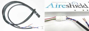
Fig 1 Wiring harness pigtail with Molex plug. Powerbox (Part # HE60-50TA) to pigtail harness connection.

Wiring Notes – Single Phase Circuit
This unit is designed for connection to a single-phase branch circuit. The module is internally isolated and the line (hot) and neutral conductors are electrically interchangeable at the power input terminals.
- Connect either supply conductor to either terminal marked L/N.
- Ensure that the equipment ground is connected to the designated ground terminal at all times.
- Supply voltage must match the nameplate rating (e.g., 120 VAC or 220–240 VAC, single-phase).
- Use copper conductors only, sized per NEC/CEC and all local electrical codes.
- Disconnect power at the service disconnect before wiring or servicing.
Important Safety Notice: Although line and neutral are interchangeable at the unit input, the branch circuit must still be wired in compliance with NFPA 70 (NEC), CSA C22.1 (CEC), and all local codes.
The disconnecting means must clearly open the supply line conductor(s).
5.2.2 Powerbox Settings
Airflow Proving Switch: The Aireshield includes a factory-wired airflow-proving switch. To bypass (for constant fan operation or troubleshooting), install the supplied jumper (Fig. 2) on JP-AIR (Fig. 3).

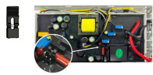
Fig.2. Bypass jumper. Typically taped inside of the powerbox. |
Fig. 3. JP-AIR proving switch (circular photo inset) with bypass jumper location.
5.3 Electrical Connection — Multiple Modules (Manifold Wiring)
Overview
Each Aireshield module is supplied with a 3-ft pre-terminated pigtail harness. For installations with two or more modules, terminate each module’s pigtail at a terminal/power block (manifold) inside the air handler control panel. From that block, run one set of conductors to a suitable power source in the unit control panel.
- Safety & Preparation
- Power Off
De-energize the HVAC system at the main breaker and apply lockout/tagout per site procedure.
- Verify Voltage
Confirm the available supply matches the Aireshield nameplate rating (110-120 VAC or 220–240 VAC, single-phase). Please note, the Aireshield can handle 50 or 60 hertz power frequency.
- Select Mounting Location for Terminal Block
Mount a listed terminal/power distribution block inside the control panel: (Note, if the terminal block is mounted inside the air handler, please make sure it is rated and configured accordingly for safety.
- On a rigid backplate/rail (DIN rail acceptable if listed)
- Away from moving parts, sharp edges, and high-heat zones
- In a serviceable location for inspection and troubleshooting
- Plan Conductor Routing
Plan a clean path for each module pigtail into the control panel. Avoid routing alongside high-noise motor leads when possible.
If penetrating a metal wall, use appropriate grommets
- Route Module Harnesses into the Control Panel
- Routing
Pass each module’s pre-terminated harness through a ⅜” rubber grommet (or listed strain-relief fitting) into the control panel.
- Strain Relief & Dress
Secure each harness with zip ties or wire saddles so no tension is placed on terminations and the harness cannot contact hot or rotating components.
- Terminate Multiple Modules at the Terminal Block (Manifold)
Goal: All module “line” conductors land together on one block position, all “neutral” together on another, and all grounds to the ground bar/chassis.
- Identify Conductors (per module pigtail)
- Line (red/brown)
- Neutral (blue)
- Ground (green/yellow)
- Land Each Module to the Terminal Block
- Terminate each module’s Line (red/brown) to the LINE distribution position on the terminal block.
- Terminate each module’s Neutral (blue) to the NEUTRAL distribution position on the terminal block.
- Terminate each module’s Ground (green/yellow) to the equipment ground bar (preferred) or designated chassis ground point.
- Torque & Verify
- Tighten all terminals to the terminal block manufacturer’s torque specification.
- Perform a firm pull test on each conductor.
- Confirm no copper is exposed outside the clamp area.
- Feed the Terminal Block from the Air Handler Power Source
- Install the “Feed” Conductors
From the terminal block, run one set of appropriately sized copper conductors to the selected power source:
- LINE feed from terminal block LINE position → unit power source (L1/L2 as applicable)
- NEUTRAL feed from terminal block NEUTRAL position → unit neutral (if present)
- GROUND remains bonded to chassis/ground bar
- Choose an Acceptable Power Source
- Non-Residential (Typical): Connect to fan motor L1/L2, or a fused power strip inside the unit, or another clean fused source inside the control panel.
- Use a power source downstream of the fuse (preferred) and consistent with unit design and local code.
- Optional: Interlock With Fan Operation (Recommended)
Where practical, feed the Aireshield terminal block from a circuit that is energized only when the supply fan is energized (e.g., fan contactor load side). This ensures the modules operate during airflow.
- Final Checks & Commissioning
- Inspect Wire Management
- Harnesses secured and protected at panel entry
- No contact with sharp edges or moving components
- Terminal block cover installed (if provided/required)
- Restore Power & Verify Operation
- Re-energize the air handler
- Confirm Aireshield modules energize as intended (per unit indicators/verification procedure in IOM)
- Verify no nuisance trips and no wiring heat/odor
Wiring Notes — Single-Phase Circuit (Applies to Multi-Module Manifold)
- Designed for connection to a single-phase branch circuit.
- The module input is internally isolated; line and neutral are electrically interchangeable at the module input terminals (L/N).
- Ground must be connected to the designated equipment ground at all times.
- Supply voltage must match the module nameplate (e.g., 120 VAC or 220–240 VAC, single-phase).
- Use copper conductors only, sized per NEC/CEC and local codes.
- Disconnect power at the service disconnect before wiring or servicing.
⚠️ Important Safety Notice: Although line and neutral are interchangeable at the unit input, the branch circuit must still be wired in compliance with NFPA 70 (NEC), CSA C22.1 (CEC), and all local codes. The disconnecting means must clearly open the supply line conductor(s).
5.4 Powerbox Detailed
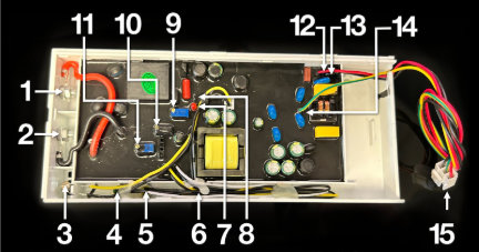
Fig. 4. Powerbox labeled diagram:
1 High Voltage Output | 5 Yellow LED (Needs Cleaning) | 9 Air Flow Sensitivity POT | 13 Black – Neutral Power |
2 High Voltage Neutral | 6 Red LED (Error / Off) | 10 Current Output Adjust POT | 14 Yellow / Green – Ground |
3 Air Flow Sensor Probe | 7 Air Flow Indicator LED | 11 Voltage Output Adjust POT | 15 Pigtail / Patch Cable Connector |
4 Green LED (Working/On) | 8 Air Flow Bypass Jumper | 12 Red – Live Power |
5.5 Standoff installation
Electrical Isolation Precaution
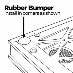
Reviveaire supplies an installation kit that includes rubber bumpers and female spade connectors (wire stacons). In certain HVAC configurations, the filter track or nearby metal components may come into contact with the backplate of the Aireshield, potentially causing electrical arcing.
To prevent this, install the provided rubber bumpers on the four corners of the Aireshield’s backplate (the side opposite the pins). These bumpers ensure proper clearance between the unit and any conductive metal surfaces. See Fig.5 for bumper placement.
Fig.5 Bumper placement.

5. Installation
Important: Ensure all rubber bumpers, supplied with each Aireshield (corners and midpoint), are in place on the back of the Aireshield, with pins pointing away. The back plate must not come into contact with bare metal inside the HVAC unit.
Verify the Aireshield size matches the filter rack. If a standard size is not available, contact Reviveaire for a custom unit.
Install the Aireshield in the return air or mixed air inlet of the HVAC system (see Fig. 1). The unit connects to the air handler/furnace power supply. It operates in unison with the system fan to ensure airflow passes over the module. Depending on local electrical codes, additional wiring and a disconnect switch may be required.
If Aireshield is used with another particulate filter, please ensure that Aireshield is installed upstream of the particle filter. The agglomeration of ultrafine particles performed by Aireshield will enhance the capture efficiency of the downstream filter.
Alternate installation points are possible, including return air grilles, supply registers, or any location within the ductwork with consistent airflow. Always follow the marked airflow direction.
Fig. 1. Typical Aireshield installation. Note proper airflow direction.
6 Commissioning Checklist
¤ Module fully seated and secured; spacer bumpers used if necessary.
¤ Rubber bumpers installed on corners and midpoint.
¤ Harness not under strain or rubbing against sharp edges.
¤ Green LED indicates fan operation. If off, confirm wiring.
¤ NO abnormal noise or odor; If YES, immediately power off
¤ For odor – check for foreign material on the pin side.
¤ For arcing/noise – ensure no metal is within 1” (25 mm)
of the Aireshield face. Verify spacer bumpers are in place.
¤ Installation date recorded on warranty card. _______________
7 Warranty Registration QR

Scan the QR code and Fill out the online warranty form. Print and retain a copy for your records and or your customer.
Reviveaire LLC,
217 Market Street,
Kenilworth NJ 07033
8 Operation
- Power Safety Turn off the power breaker to the air handler/furnace and confirm power to the air handler or furnace is de-energized before servicing the Aireshield.
- Open access to the Aireshield device. If installed in an air handler unit, select either of the following:
- Open-hinged access doors (ports) on the air handler provide access to view the Aireshield device.
- If the panel is screwed in, unscrew the air handler’s access door (ports) to access and view the Aireshield device.
- If used in a return air grill or return air to a ceiling unit, please unclip the grill via buttons or tension clamps to access and view the Aireshield device.
- If a residential furnace is used to house the Aireshield, simply unhinge the access to the filter/coil section to access and view the Aireshield device.
- If the filter is located in the return air opening before the air handler, simply remove the door cover and slide the device out. Please take care when removing the device to ensure the wires are not jammed.
- Electrical connection
- Locate the air handler/furnace power box, open the power box panel, and identify the power wiring for Ground, Neutral, L1, L2, and L3.
- Before wiring, shut off power to the air handler/furnace and verify with an amp meter or other tester that it’s completely off.
- Connect the Aireshield power line to L2 and the blue (neutral) line to N on the air handler/furnace electrical strip. Finally, attach the grounding wire to the unit’s ground terminal.
- The factory setting of the power supply
- By default, the power supply waits for airflow before activating the Aireshield. To bypass the airflow sensor, insert the jumper cap as shown in Appendix Fig. 2.
9 Troubleshoot & Maintenance
Troubleshooting | Frequency | Procedure |
Visual Inspection | Every 6 months, perform cleaning with the wool tool or water wash. | Disconnect power. Slide the module out. Remove the Mesh on the upstream side. Wipe honeycomb surfaces with a soft, lint-free cloth dampened with 70% rubbing alcohol; avoid bending pins. Allow to dry completely. Perform drill bit cleaning with the wool tool or water wash. |
LED Yellow | Immediate cleaning is required. Otherwise, clean every 6 months as described above. | *See above for cleaning methods |
LED Red | Inspected if the Aireshield is not working or during the 6-month cleaning period | If the red LED is illuminated, the device has encountered a problem and is not functioning correctly. Typically, this can be due to a foreign object short-circuiting the device. Inspect the device to ensure it is free from foreign matter and perform the cleaning as noted above. |
Maintenance Task | Frequency | Procedure |
Alternate Cleaning Method | Every 6 months | Disconnect power. Slide the module out. Remove the Mesh on the upstream side. Wipe honeycomb surfaces with a soft, lint‑free cloth dampened with 70 % rubbing alcohol; avoid bending pins; allow to dry completely |
Electrical test (contractor) | Annually | Measure primary voltage (diagnostic port) ≈ 5.5 kV ±10 % |
None expected under regular use (10‑year design life) | None expected under regular use (10‑year design life) | |
Tip: Set a calendar reminder or ask Reviveaire to enroll you in our free maintenance‑alert program.
10 Specifications
Model name | Aireshield |
Rated voltage | 120–240VAC |
Rated frequency | 50/60Hz |
Thickness | 0.875 Inch |
Live SARS Virus test | ≥ 99.9% * |
Staphylococcus albus kill rate | ≥ 99.9% ** |
Natural bacteria death rate | ≥ 90% *** |
Ozone concentration UL2998 | Intertek – Certified Zero Ozone **** |
California Air Resources Board | Aireshield is CARB approved |
Local Code Jurisdiction | Local code minimum outdoor airflow design should be complied with.) |
Operating Temperature | 32 °F – 140 °F (0 °C – 60 °C) |
Service Life | 10 Years |
10.1 Efficacy Ratings
Live SARS Virus test | ≥ 99.9% * |
Staphylococcus albus kill rate | ≥ 99.9% ** |
Natural bacteria death rate | ≥ 90% *** |
Note:
* Innovative Bioanalysis Live SARS test
** Proved in the simulated field experiment of air sterilization, the killing rate of staphylococcus albus was 99.98%
after the Aireshield has run for 2 hours
*** Proven in the simulated field experiment of air sterilization, the killing rate of Natural Bacteria 99.98%
after the Aireshield has run for 2 hours.
**** UL-2998 certified by Intertek Certified Zero Ozone
11. Limited Warranty
Coverage
Reviveaire warrants each Aireshield® air disinfection module to be free from defects in materials and workmanship for 36 months from the date of installation, or 42 months from the date of manufacture, whichever occurs first.
This warranty applies to both residential and non-residential applications, including those purchased directly through Aireshield.com or installed by a certified HVAC professional. Remember to register your product at https://reviveaire.com/warranty-card
Eligibility and Conditions
Warranty coverage applies when:
- The Aireshield module is installed and maintained according to the instructions in the official Installation & Operation Manual (IOM).
- The unit is installed by either:
(a) a licensed HVAC contractor or authorized Reviveaire channel partner, or
(b) the end user (DIY installation), provided the product is not altered, rewired, or used outside its intended purpose.
- The warranty covers parts only. All labor, service, diagnostic, and shipping or freight costs for removal, return, or reinstallation are the responsibility of the owner or end user.
- The warranty is transferable with property ownership, provided the Aireshield remains installed and properly maintained.
Reviveaire’s Obligation
If a covered defect is confirmed during the warranty period, Reviveaire will, at its discretion, repair or replace the defective module or component at no charge for materials. The balance of the original warranty period will remain in effect for the repaired or replacement unit.
Exclusions and Limitations
This warranty does not cover:
- Damage caused by improper installation, misuse, negligence, modification, or operation outside of Reviveaire’s published specifications.
- Exposure to corrosive, explosive, or hazardous environments.
- Damage resulting from improper electrical wiring, unclean or unstable power, or use with non-approved power sources.
- Units not maintained in accordance with the IOM or subjected to physical abuse.
This warranty applies only to the Aireshield module itself and excludes all incidental or consequential damages, including associated labor, materials, or shipping.
No other warranties, expressed or implied—including merchantability or fitness for a particular purpose—apply beyond those stated herein.
Download the Latest Manual.
This Version 13 | 12-23-25
© 2025 Reviveaire LLC | 217 Market St, Kenilworth NJ 07033 | +1 908‑987‑7089 | info@reviveaire.com
www.reviveaire.com/aireshield-manual/
You are what you breathe. Breathe Safer.
Warranty Service & Support
Handle the Aireshield module carefully to avoid physical damage or injury.
For service or warranty inquiries email support@reviveaire.com
reviveaire.com | aireshield.com
Related Reading:
Related Reading: Explore More About Aireshield Plasma Powered Air Disinfection
Pillar Knowledge Content:
- Indoor Air Quality – Health Wellness Guide
- HVAC Retrofits for Cleaner Air – A Homeowner’s Guide to IAQ
- Sustainable HVAC Filtration Efficiency Guide
- The True Cost Of Air Filtration – Aireshield ROI
Indoor Air Quality Categories:
- Health & Wellness
- HVAC Upgrades & Retrofits
- Sustainability & Efficiency
- Cost & ROI
- Product Support & How-To
Your Home is More than Walls & Windows
It’s where your family grows & thrives. Why not make it a healthy sanctuary?
- Shop Aireshield Now →
- Why Indoor Air Quality Matters More Than Ever →
- Energy Savings with Plasma Filtration vs. HEPA →
- Reducing Your Carbon Footprint Through Indoor Air Quality →
Wellness Starts with Every Breath
Your home is more than walls and windows—it’s where your family grows, rests, and thrives. Why not make it a sanctuary for health too?
Shop Aireshield Now →
Find a Certified Installer →
You are what you breathe. Breathe Safe.
